EN

Leakage Rate Modeling for API 526/527 Safety Relief Valves: A Practical Engineering Approach
Shanghai Xiuzhao Valve · Technical note for safety valve engineers and procurement professionals
API 527 settles one question: whether a valve passes its seat tightness test. It does not answer the question a specification engineer or a procurement lead has to defend during bid evaluation — whether the next two hundred valves will pass, and with what probability. That gap is where warranty arguments and site leak reports begin.
This article converts leakage from a pass/fail observation into a modeled output: a transfer function built from parameters the manufacturer controls, calibrated against the API 527 air test, and used before the valve reaches the test stand.
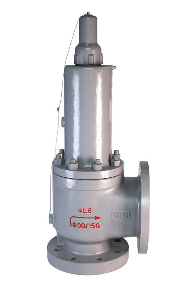
API 526 flanged steel spring-loaded pressure relief valve after final assembly; the body casting carries the orifice and pressure-class marking.
1. What API 527 fixes — and what it leaves to you
The air test is tightly specified in Clause 2. Leakage is collected through a tube of 7.9 mm (5/16 in.) outside diameter and 0.89 mm (0.035 in.) wall, cut square and smooth, held 12.7 mm (1/2 in.) below the water surface. The medium is air or nitrogen at ambient temperature. Test pressure is 90% of set pressure above 345 kPa g (50 psig), and 34.5 kPa (5 psi) below set at or below that threshold. Pressure is held 1 minute for NPS 2 and smaller, 2 minutes for NPS 2½ through 4, and 5 minutes for NPS 6 and larger, after which bubbles are counted for at least one minute — observed through a mirror, never with the face in line with the outlet.
Scope runs from 103 kPa g to 41,379 kPa g (15 to 6,000 psig). For metal seats, Table 1 sets the ceiling in bubbles per minute:
Set pressure, psig |
Orifice ≤ 18 mm |
Orifice 18 mm |
API approx. leakage, sm³/24 h |
15–1,000 |
40 |
20 |
0.017 |
1,500 |
60 |
30 |
0.026 |
2,000 |
80 |
40 |
0.034 |
2,500–6,000 |
100 |
50–100 |
0.043 |
Note where the line sits: the valve itself — body, orifice designation D through T, flange facing, capacity — is an API 526 item; seat tightness is an API 527 item. A purchase order that cites only API 526 has specified geometry and capacity, not tightness.
Two commercial consequences follow. First, the allowance is not a single number: at 300 psig, a valve with an orifice of 18 mm or less may leak 40 bubbles/min, while a larger-orifice valve at the same pressure is allowed only 20 — the tighter figure sits on the bigger body. Second, Table 1 is a floor, not a target. Clause 1 states that where greater tightness is required, the purchaser shall specify it in the purchase order. That sentence is the legal basis for every acceptance criterion you write.
For soft-seated valves the limit is zero bubbles for one minute. Steam service requires no audible or visible leakage. The water test permits 10 cm³/h per inch of nominal inlet size.
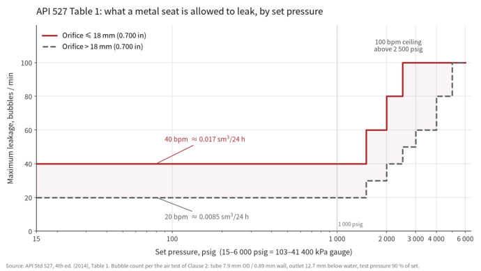
Figure 1. API 527 (4th ed.) Table 1 limits plotted against set pressure. The allowance steps up at 1,500 psig and reaches its 100 bubble/min ceiling at 2,500 psig.
2. Convert the acceptance criterion to SI before modeling
Bubble counting is a shop-floor proxy. Your emissions calculation, vendor warranty, and O&M documentation are written in mbar·L/s or sccm. The working bridge: 1 bubble per second ≈ 1.01 × 10⁻³ mbar·L/s, and 1 bubble per 100 seconds ≈ 1.01 × 10⁻⁵ mbar·L/s. On that basis the default 20–40 bubbles/min band is about 3.4 × 10⁻⁴ to 6.7 × 10⁻⁴ mbar·L/s, and the 100-bubble ceiling about 1.7 × 10⁻³ mbar·L/s.
For a pressure relief valve leakage rate quoted this way, the number also becomes auditable: it can be compared against an LDAR threshold, a flare-header allowance, or a warranty clause without re-running a bubble count.
The conversion is order-of-magnitude, and should be labeled as such. Bubble volume depends on tube geometry and surface tension; a 60-second count resolves roughly ±1 bubble; the same physical leak reads differently on a wet or dry outlet. Use it to compare bids and to draft a leak-rate clause — not to claim a calibrated measurement.
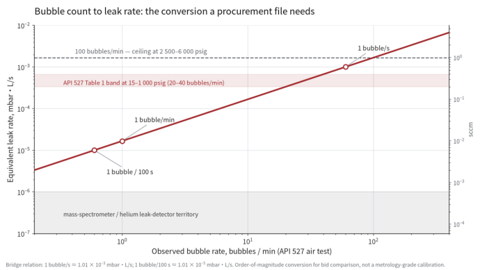
Figure 2. Bubble count versus equivalent leak rate. The 20–40 bubble/min band of Table 1 maps to roughly 3.4–6.7 × 10⁻⁴ mbar·L/s.
3. Parameters that actually move the bubble count
Narrow the factor list to what a valve factory can control and measure in process:
Parameter |
Typical controlled range |
Mechanism |
Seat flatness |
0.5–3 µm (optical flat / light band) |
decides line versus area contact; a 2 µm wave across a 40 mm seat opens a channel no torque can close |
Ra |
0.05–0.4 µm |
baseline asperity height feeding the leak path |
Rpk / Rvk (ISO 13565) |
0.1–1.0 µm |
plateau and valley volume: valleys store gas, then release it as counted bubbles |
Seating contact width |
0.3–1.5 mm |
sets unit seating load; too wide loses contact pressure, too narrow risks brinelling |
Hardness differential |
≥ 3–5 HRC between disc and nozzle |
limits galling and scratch generation after pop cycles |
Alignment and preload |
nozzle-to-disc ≤ 0.05 mm; controlled bolt torque sequence |
asymmetric preload tilts the disc and opens one side of the seat |
Why include Rvk and not Ra alone. Near 1 bar the mean free path of air is about 68 nm, comparable to the seat gap. Across a 0.1–1 µm gap the Knudsen number falls from 0.68 to 0.068 — slip flow shading into early transition, where molecular transport depends on the shape of the surface rather than its average roughness. Mean free path scales inversely with pressure, so at 60 bar the same gap sits in continuum flow; the rarefied regime matters at the low-pressure end of Table 1, which is exactly where the tightest bubble limits apply. Two seats with identical Ra can differ by a factor of three in leakage if their valley volumes differ.
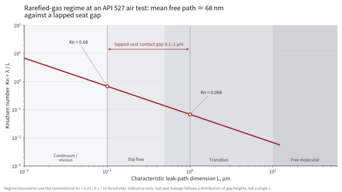
Figure 3. Knudsen number against seat gap at about 1 bar. A 0.1–1 µm lapped contact sits in slip flow and early transition, which is why valley-volume parameters enter the model.
4. Sample size and model family
Bubble counts are discrete, zero-heavy, and observer-dependent. Ordinary least squares is the wrong default.
- Response variable: bubbles per minute, integer 0–100, one row per test.
- Minimum sample: about 10 observations per candidate predictor for stable OLS coefficients — 12 predictors means roughly 120 tests. A negative-binomial GLM or ridge-regularized model is workable at 60–80 tests, which most factories already hold in historical records.
- Stratify by set-pressure band and orifice class; carry observer ID and test stand as random effects.
- Inputs: API 527 test sheets, seat inspection records (flatness, Ra/Rvk, hardness), and assembly records (torque values, spring lots).
5. Model form and the gates it must pass
Predicted bubble count = β₀ + β₁·Ra + β₂·flatness + β₃·contact width + β₄·hardness difference + … + ε
Gates for procurement use:
- Hold-out R² ≥ 0.70 on the parameters the supplier controls.
- Residuals show no trend against set pressure or orifice class.
- 95% prediction interval half-width ≤ 50% of the applicable Table 1 limit.
- Cpk ≥ 1.33 for predicted bubble count against the contractual limit, computed per set-pressure band.
A model that cannot clear the third gate is a screening tool, not a release criterion. That is still worth having — provided the technical file says so.
6. What the model cannot do
- It does not replace the API 527 test. Conformity is demonstrated by test, not by regression.
- Coefficients do not transfer to another supplier's process without refitting.
- Without time-series data it cannot predict degradation after thermal cycling, fouling, or repeated pops.
7. Three questions for a bid evaluation
- What is your demonstrated Cpk for API 527 bubble count in my set-pressure and orifice band? A supplier who answers with a number has the data. One who answers "100% tested" has a test, not a capability.
- Which seat parameters do you control, at what limits, and how are they recorded? Ra alone is insufficient for metal seats; ask for flatness and Rvk.
- Can you state your bubble-count criterion as a leak rate in mbar·L/s? If the answer is "zero bubbles", ask which detection limit that corresponds to.
Shanghai Xiuzhao Valve manufactures API 526-compliant flanged steel pressure relief valves with seat tightness documented to API 527. Send your set pressure, orifice designation, and required leak rate to our engineering team for a specification review.
|
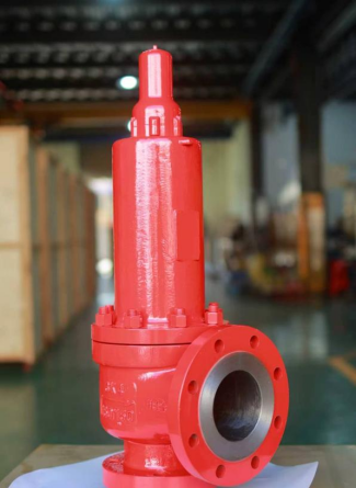
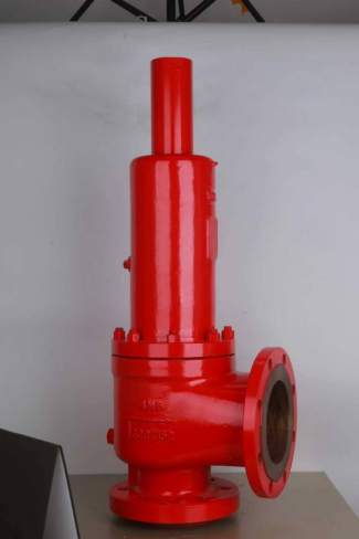
Closed-bonnet flanged pressure relief valve after final red spray coat. |
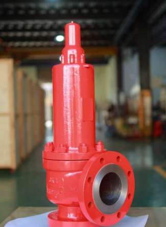
Finished valve in the assembly shop; the stainless RTJ outlet face is visible. |
Keywords: API 526 safety valve, API 527 seat tightness, pressure relief valve leakage rate, safety valve procurement, relief valve regression model, mbar L/s conversion, metal seat leakage
Table of Contents
- Leakage Rate Modeling for API 526/527 Safety Relief Valves: A Practical Engineering Approach
- 1. What API 527 fixes — and what it leaves to you
- 2. Convert the acceptance criterion to SI before modeling
- 3. Parameters that actually move the bubble count
- 4. Sample size and model family
- 5. Model form and the gates it must pass
- 6. What the model cannot do
- 7. Three questions for a bid evaluation